
Part F ventilation: what homeowners and builders must do
Part F ventilation: what homeowners and builders must do
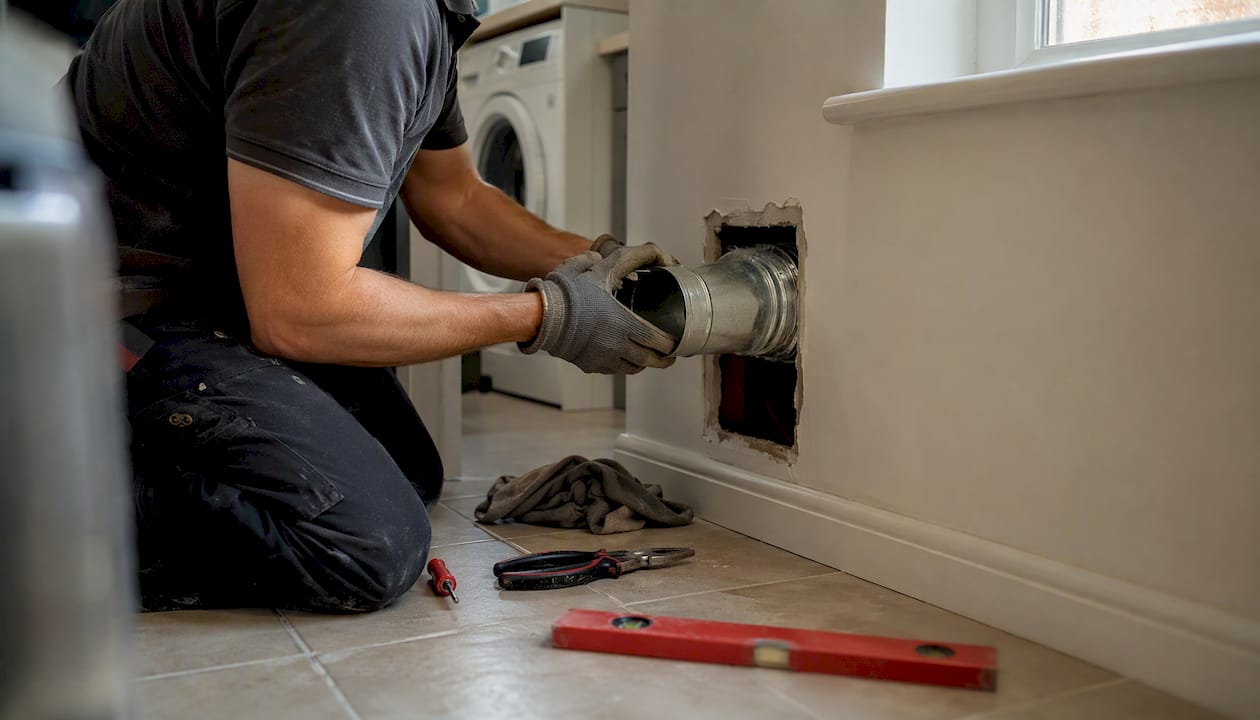
Approved Document F requires every dwelling to provide three things: extract ventilation in wet rooms, whole-dwelling background ventilation, and purge ventilation in every habitable room. If you are building, extending, or carrying out notifiable work on a home in England, you must satisfy all three aims and hand documented evidence to Building Control before the job is signed off.
Here is what that means in practice:
- Extract ventilation: fit intermittent extract fans in kitchens, bathrooms, utility rooms, and sanitary accommodation at rates specified in the Approved Document. Continuous extract systems must meet the lower continuous rates set out in the Approved Document tables.
- Whole-dwelling ventilation: supply a minimum of 0.3 l/s per m² of internal floor area across the dwelling, or meet the bedroom-based minimums in Table 1.3, whichever is greater.
- Purge ventilation: every habitable room must be capable of at least 4 air changes per hour directly to outside, typically via openable windows sized to the guidance in BS 5925.
- Commissioning: any mechanical ventilation system must be commissioned by a competent person, with measured airflow rates recorded and a commissioning sheet submitted to Building Control.
For the full statutory text and downloadable tables, use Approved Document F Volume 1 alongside the Domestic Ventilation Compliance Guide, which provides the model commissioning forms.
Key takeaways
Part F requires extract ventilation, whole-dwelling background ventilation, and purge ventilation in every dwelling, with measured commissioning evidence submitted to Building Control for all mechanical systems.
| Point | Details |
|---|---|
| Extract rates to check | Bathrooms need at least 8 l/s; kitchens need at least 13 l/s from an intermittent fan. |
| Whole-dwelling supply | Calculate 0.3 l/s per m² of floor area and compare with the Table 1.3 bedroom minimum; use the higher figure. |
| Purge ventilation target | Every habitable room must achieve at least 4 air changes per hour directly to outside. |
| Commissioning is mandatory | Measured airflow rates must be recorded on an Appendix C sheet and submitted to Building Control. |
| Quaypointplastering surveys | Survey-led diagnosis across Dorset, Hampshire, and Wiltshire identifies Part F shortfalls and delivers commissioning-ready remedial works. |
Table of Contents
- What does Part F cover, and which volume applies to your project?
- What are the three core aims under Part F ventilation?
- What ventilation rates does the Approved Document specify?
- Which ventilation system types meet Part F requirements?
- What does good commissioning look like, and what will Building Control check?
- How do you minimise external pollutants entering through ventilation intakes?
- How does Part F apply to work on existing dwellings?
- What evidence do you need to submit to Building Control?
- When ventilation failure causes mould: a survey-led approach
- What surveyors see most often in Part F failures
- Quaypointplastering: survey-led ventilation diagnosis across Dorset, Hampshire, and Wiltshire
- Sources
What does Part F cover, and which volume applies to your project?
Part F of the Building Regulations 2010 sets Requirement F1(1): buildings must be designed and constructed to provide adequate means of ventilation for the people in them. The Approved Document is the government’s guidance on how to meet that requirement. It is split into two volumes:
- Volume 1: Dwellings covers houses, flats, and any building used wholly or mainly as a dwelling, including extensions and material changes of use. This is the volume most homeowners, builders, and architects will work from.
- Volume 2: Buildings other than dwellings covers offices, schools, retail, and other non-domestic buildings.
Both volumes are available as free PDF downloads from gov.uk. Volume 1 is the primary reference for the rates, tables, and commissioning requirements discussed throughout this article.
Transitional arrangements and effective dates
The current Approved Document F was updated in 2021 (for England) and again in 2026. Circular Letters published alongside the documents set out the exact dates from which each version applies and the transitional arrangements for projects where a building notice, full plans application, or initial notice was submitted before the new version came into force. If your project straddles an update date, check the Circular Letter on gov.uk to confirm which version governs your submission.
Alternative solutions
The Approved Document is guidance, not the only route to compliance. You may use an alternative ventilation solution provided you can demonstrate to the building control body that it satisfies Requirement F1(1) to an equivalent standard. That demonstration must be documented and submitted in the same way as a standard compliance submission.
What are the three core aims under Part F ventilation?
Approved Document F Volume 1 structures its guidance around three distinct ventilation aims. Each has its own performance target, and each requires different hardware or design provision.
Extract ventilation
Extract ventilation removes moisture and pollutants at source, before they spread through the dwelling. It is required in:
- Kitchens (including open-plan kitchens where cooking takes place)
- Utility rooms
- Bathrooms and shower rooms
- Sanitary accommodation (WCs)
Extract can be intermittent (a fan that runs during and briefly after use) or continuous (a fan running at a low background rate with a boost function). The minimum rates differ between the two modes and are set out in Tables 1.1 and 1.2 of the Approved Document.
Whole-dwelling (background) ventilation
Background ventilation provides a continuous, low-level supply of fresh air to every room in the dwelling. The target is to dilute pollutants that build up over time: CO₂ from occupants, volatile organic compounds from furnishings, and residual moisture. The minimum supply rate is 0.3 l/s per m² of internal floor area, with a floor set by the bedroom-based minimums in Table 1.3. Where the two methods give different answers, you use whichever produces the higher total supply rate.
Background ventilation is typically delivered through trickle vents in windows, background ventilators in walls, or the supply side of a mechanical system such as MVHR or PIV.
Purge ventilation
Purge ventilation is for rapid dilution of high concentrations of pollutants or moisture, such as after painting, cleaning, or a cooking incident. Every habitable room must be capable of achieving at least 4 air changes per hour directly to outside. In most rooms this is achieved by openable windows; the Approved Document gives minimum opening areas based on BS 5925 assumptions. In rooms without external walls (internal bathrooms, some basement conversions), purge must be delivered mechanically, because openable windows are not an option.
Pro Tip: Purge ventilation is often the aim that gets overlooked on drawings. Check every habitable room on the floor plan, not just the wet rooms, and confirm that each has either an openable window of adequate area or a mechanical extract rate that achieves 4 ACH.
The table below maps each aim to the typical compliant provision and the evidence Building Control will expect.
| Ventilation aim | Typical compliant provision | Evidence required |
|---|---|---|
| Extract ventilation | Intermittent or continuous extract fan in wet rooms | Measured airflow rate, commissioning sheet |
| Whole-dwelling background ventilation | Trickle vents, background ventilators, or mechanical supply | Calculation showing 0.3 l/s/m² or Table 1.3 bedroom minimum met |
| Purge ventilation | Openable windows (min. area per BS 5925) or mechanical extract at 4 ACH | Opening area schedule or measured mechanical rate |
What ventilation rates does the Approved Document specify?
The numbers below come directly from Approved Document F Volume 1. These are the figures Building Control will check against your commissioning sheet.
Intermittent extract rates (Table 1.1)
- Kitchen: 13 l/s adjacent to the hob, or 30 l/s elsewhere in the kitchen
- Utility room: 8 l/s
- Bathroom (including shower room): 8 l/s
- Sanitary accommodation (WC only): 6 l/s
These are minimum rates. A fan that delivers less than these figures at the installed duct length and resistance will not comply, which is why measured commissioning matters.
Continuous extract rates (Table 1.2)
Continuous systems operate at two rates: a normal (background) rate and a boost rate triggered by occupancy or humidity. The boost rate must meet or exceed the intermittent rates above. The normal rate is lower and contributes to the whole-dwelling supply total.
Whole-dwelling ventilation (Table 1.3)
The whole-dwelling supply must meet both of the following:
- Floor-area method: 0.3 l/s per m² of total internal floor area
- Bedroom method: a minimum total supply rate based on the number of bedrooms (Table 1.3 sets these out; a one-bedroom dwelling has a lower minimum than a four-bedroom dwelling)
You use whichever calculation gives the higher total.
Worked example 1: two-bedroom semi-detached house
- Total internal floor area: 72 m²
- Floor-area calculation: 72 × 0.3 = 21.6 l/s
- Table 1.3 bedroom minimum for two bedrooms: 13 l/s (check the current table for the exact figure)
- Required whole-dwelling supply: 21.6 l/s (floor-area method governs)
Worked example 2: three-bedroom flat
- Total internal floor area: 85 m²
- Floor-area calculation: 85 × 0.3 = 25.5 l/s
- Table 1.3 bedroom minimum for three bedrooms: 17 l/s
- Required whole-dwelling supply: 25.5 l/s (floor-area method governs)
Purge ventilation opening area
For a typical urban living room of 20 m² with a ceiling height of 2.4 m, the room volume is 48 m³. To achieve 4 ACH, the room needs to exchange 192 m³/h of air. The Approved Document’s BS 5925-based guidance translates this into a minimum openable window area; the exact figure depends on the window type and opening geometry. As a rule of thumb, an openable area equal to 1/20th of the floor area will generally satisfy the requirement for most standard rooms, but always verify against the Approved Document tables for the specific room.
Which ventilation system types meet Part F requirements?
There is no single prescribed system. The Approved Document sets performance targets; you choose the system that meets them for your project. Each type has a different profile of strengths, limitations, and installation requirements.
Natural ventilation
Natural ventilation relies on openable windows for purge and trickle vents or background ventilators for continuous background supply. It is the simplest and lowest-cost option for dwellings with reasonable air permeability. The limitation is that it depends on wind pressure and temperature differentials; it cannot reliably deliver a guaranteed continuous rate in all weather conditions. Designers should not assume occupant behaviour (opening windows) will satisfy continuous background ventilation rates.
Intermittent extract fans
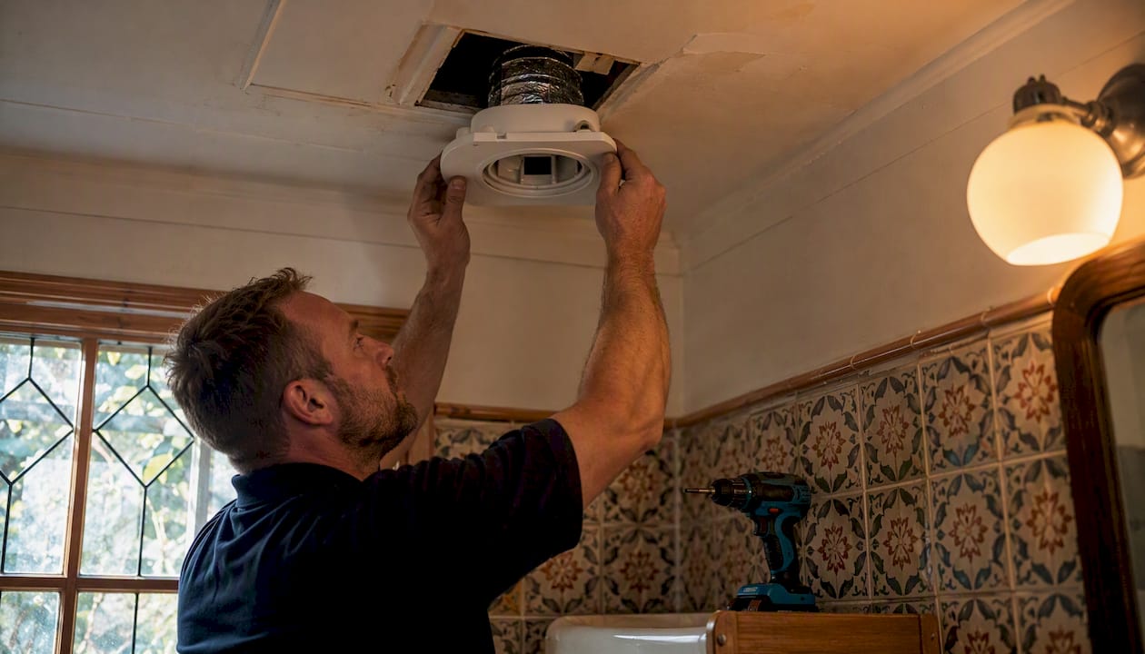
Intermittent fans in wet rooms, combined with trickle vents for background supply, form the most common system in new and refurbished UK dwellings. They are straightforward to install and commission. The key compliance risk is duct resistance: a fan that meets its rated output in free air may fall below 8 l/s or 13 l/s once installed with bends, long duct runs, and a terminal. Measured commissioning is not optional.
Continuous mechanical extract (MEV/CMV)
A centralised mechanical extract ventilation system draws air continuously from all wet rooms through a single fan unit, with trickle vents or background ventilators providing the supply. MEV is well suited to retrofit projects where individual room fans are impractical and where the dwelling has reasonable background ventilator provision. It is less effective in very leaky dwellings where uncontrolled infiltration undermines the designed supply paths.
Mechanical supply and extract with heat recovery (MVHR)
MVHR supplies filtered, tempered fresh air to habitable rooms and extracts stale air from wet rooms, recovering heat in the process. It is the preferred system for highly airtight dwellings (typically those built to Passivhaus or Part L 2021 standards) where natural infiltration cannot be relied upon for background supply. MVHR requires careful duct design, balancing, and commissioning; an unbalanced system can create positive or negative pressure imbalances that cause doors to slam and draughts. For energy efficient ventilation solutions in new-build or deep-retrofit projects, MVHR offers the best combination of air quality and heat retention.
Positive Input Ventilation (PIV)
PIV systems introduce filtered air from the loft or outside into the dwelling at a central point, typically a hallway, creating a slight positive pressure that pushes stale air out through gaps and trickle vents. PIV is widely used as a retrofit condensation control measure. It does not extract from wet rooms directly, so it must be combined with adequate extract fans to meet the extract ventilation aim. PIV alone does not satisfy all three aims of Part F.
The comparison below summarises the key characteristics of each system type.
Installation notes
Extract terminals should be positioned as high as practicable in the room and no more than 400 mm below the ceiling, to capture the warm, moist air that rises. Cooker hoods that extract to outside must be positioned at the correct height above the hob as specified in the Approved Document and the hood manufacturer’s instructions. Never allow an extract terminal to discharge into a roof void, loft, or cavity; it must terminate outside the building envelope.
What does good commissioning look like, and what will Building Control check?
Commissioning is where many Part F submissions fall short. The hardware may be correct, but without measured airflow evidence, Building Control cannot accept the installation as compliant.
What commissioning requires
- A competent person measures the actual airflow rate at each extract terminal and supply point using a calibrated anemometer or flow hood.
- Measured rates are recorded against the design rates on the commissioning sheet.
- Where measured rates fall below the minimum (for example, below 8 l/s at a bathroom fan), the cause is investigated and rectified before sign-off.
- A commissioning notice is submitted to the building control body.
- The completed commissioning sheet (based on Appendix C of the Approved Document) is provided to Building Control and to the building owner.
What Building Control expects at handover
- Measured airflow results for every mechanical terminal
- Completed commissioning sheet (Appendix C format)
- System schematic or layout drawing showing duct routes and terminal positions
- Product data sheets confirming fan performance curves
- Maintenance instructions for the occupant (filter change intervals, fan access)
- Completion certificate or sign-off from the commissioning engineer
Pro Tip: Ask for the commissioning sheet before paying the final invoice. A contractor who cannot produce measured airflow figures has not completed the job. The commissioning certificate is as important as the hardware for Building Control acceptance.
Installer checklist before handover
- Confirm all duct joints are sealed and insulated where required.
- Test each fan at the installed duct resistance, not in free air.
- Record measured rates on the Appendix C sheet.
- Check terminal positions comply with the 400 mm ceiling rule.
- Confirm cooker hood discharges to outside.
- Submit commissioning notice to Building Control.
- Leave maintenance instructions with the client.
Client checklist before accepting handover
- Request the commissioning sheet with measured figures.
- Confirm the commissioning notice has been submitted.
- Check that maintenance instructions are provided in writing.
- Verify that Building Control has acknowledged the commissioning notice.
How do you minimise external pollutants entering through ventilation intakes?
Section 2 of Approved Document F addresses a risk that is easy to overlook: the ventilation system itself can introduce external pollutants if intakes are poorly sited. This matters most in urban areas, near busy roads, industrial sites, or construction zones.
When intake location matters
- Dwellings within 50 m of a busy road or junction
- Sites near industrial emissions or waste processing
- Locations subject to construction dust during the build phase
- Basement or semi-basement dwellings where ground-level pollutants concentrate
Practical siting rules
- Position mechanical supply intakes and background ventilators away from direct vehicle exhaust paths, ideally on the least-exposed elevation.
- Avoid locating intakes at ground level on a street frontage; a higher position on a side or rear elevation reduces exposure significantly.
- Intakes should be separated from extract terminals by adequate distance to prevent short-circuiting of stale air back into the supply.
- Where CIBSE TM64 or TM40 guidance applies to the project (typically larger or more complex schemes), follow the intake siting recommendations in those documents.
When an air quality assessment is needed
The Approved Document includes pollutant limit values in Table 2.1. Where a site assessment suggests that background concentrations of NO₂, PM2.5, or other listed pollutants may approach or exceed those limits, a formal air quality assessment is appropriate before finalising the ventilation design. The assessment determines whether filtration is needed at the intake and what filter grade is required. For most standard residential projects in suburban or rural locations, an assessment is not required, but designers should document the decision.
Pro Tip: For a new-build or deep-retrofit project near a main road, specify a supply fan with a filter housing as standard. Retrofitting a filter later is significantly more disruptive and expensive than designing for it from the outset.
How does Part F apply to work on existing dwellings?
Work on existing dwellings is governed by a standard of reasonable practicability rather than the full new-build performance targets. Section 3 of the Approved Document sets out how this works in practice.
What reasonable practicability means
You are not required to upgrade the entire ventilation system whenever you carry out notifiable work on an existing dwelling. The obligation is to make the ventilation no worse than it was before the work, and to improve it where it is reasonably practicable to do so. What is reasonably practicable depends on the nature and extent of the work, the cost relative to the overall project value, and the physical constraints of the building.
Common retrofit triggers
- Replacing windows with more airtight units is one of the most frequent triggers for retrofit ventilation requirements. New double or triple-glazed windows eliminate the background infiltration that older, draughty windows provided. Without trickle vents in the new frames, background ventilation can drop significantly, leading to condensation and black mould growth.
- Adding insulation to walls or roofs increases airtightness and has the same effect.
- Converting a loft or basement into habitable space requires the new rooms to meet the full ventilation aims.
- Replacing a heating system may affect the operation of open-flued appliances and their interaction with ventilation.
Retrofit options
- Fit trickle vents in replacement window frames as the minimum background ventilation measure.
- Install a PIV unit where background ventilation is inadequate across the whole dwelling.
- Fit a centralised MEV system where multiple wet rooms lack adequate extract.
- Add individual intermittent extract fans where none exist or where existing fans are undersized.
Pro Tip: If you are replacing windows across a whole house, specify trickle vents in every frame as a standard inclusion. The cost difference is small at the time of installation; the cost of remedying condensation and mould afterwards is considerably higher.
When to engage a specialist
Where the existing ventilation is already inadequate, or where the proposed works will significantly increase airtightness, a specialist ventilation survey is advisable before finalising the specification. The survey documents existing conditions, identifies the shortfall, and produces a specification that Building Control can assess. This is particularly relevant for landlords and property managers, where ventilation-related mould can become a legal compliance issue under the Homes (Fitness for Human Habitation) Act 2018.
What evidence do you need to submit to Building Control?
Demonstrating compliance with Part F is a documentation exercise as much as a technical one. Building Control needs to see that the design meets the targets and that the installed system has been measured and found to perform as designed.
Documents Building Control will typically require
- Commissioning sheet with measured airflow rates for every mechanical terminal (Appendix C format)
- Whole-dwelling ventilation calculation showing the 0.3 l/s/m² floor-area result and the Table 1.3 bedroom-based minimum, with the governing figure identified
- System schematic or layout drawing
- Product data sheets for fans, heat recovery units, or ventilators, confirming performance at the installed duct resistance
- Maintenance instructions for the occupant
- Commissioning notice submitted to the building control body
- Completion certificate from the commissioning engineer
Presenting the whole-dwelling calculation
Set out the calculation in a simple table: list the total internal floor area, multiply by 0.3 to get the floor-area minimum, then state the Table 1.3 bedroom minimum, and identify which is higher. Then show how the installed system delivers that rate, whether through trickle vent free area, mechanical supply rate, or a combination.
Combining Part F and Part L submissions
The commissioning notice for Part F can often be submitted alongside the air permeability test results required under Part L. Many building control bodies accept a combined submission document that covers both. Confirm the preferred format with your local building control body at the pre-application stage.
| Document | What it shows | Who provides it |
|---|---|---|
| Commissioning sheet (Appendix C) | Measured airflow rates vs. design rates | Commissioning engineer |
| Whole-dwelling ventilation calculation | Floor-area and bedroom-based supply totals | Designer or architect |
| System schematic | Duct routes, terminal positions, fan locations | Designer or installer |
| Product data sheets | Fan performance at installed resistance | Manufacturer / installer |
| Maintenance instructions | Filter intervals, access points, reset procedures | Manufacturer / installer |
| Commissioning notice | Formal notification to Building Control | Installer or contractor |
When ventilation failure causes mould: a survey-led approach
Poor ventilation is one of the most consistent causes of persistent condensation and black mould in UK homes. When extract rates fall below the minimums, or when background ventilation is absent after a window replacement, moisture accumulates in the fabric of the building. The result is visible mould on cold surfaces, behind furniture, and in corners of poorly ventilated rooms. Understanding why black mould keeps returning often comes down to a ventilation shortfall that has never been properly diagnosed.
A survey-led approach addresses this systematically.
- Survey and diagnosis: A surveyor visits the property and records moisture readings at walls, ceilings, and floor junctions; notes the location and extent of mould growth; assesses the existing ventilation provision (fan types, trickle vent presence, window condition); and identifies occupant practices that may be contributing.
- Findings and specification: The survey produces a written report with documented findings, a clear diagnosis (condensation from inadequate ventilation, penetrating damp, rising damp, or a combination), and a defined scope of remedial work. For ventilation-related mould, the specification will identify the Part F shortfall and the measures needed to address it.
- Remedial works: Works may include fitting or upgrading extract fans to meet the 8 l/s or 13 l/s minimums, installing trickle vents in replacement windows, fitting a PIV unit, or specifying a centralised MEV system. Where mould has already colonised plaster or timber, mould removal and reinstatement is carried out as part of the same programme.
- Commissioning and verification: Mechanical systems are commissioned with measured airflow rates recorded. Post-works moisture readings confirm that conditions have improved.
- Documentation: The client receives a written report, the commissioning sheet, and a written guarantee covering the remedial works.
Pro Tip: Do not treat mould as a decorating problem. If the ventilation shortfall is not corrected, mould will return within months regardless of how thoroughly the surface is cleaned. A documented survey is the only way to confirm the cause and specify a lasting solution.
What surveyors see most often in Part F failures
The same failures appear repeatedly on site, and most of them are avoidable with straightforward checks at the right stage of a project.
The most common is insufficient commissioning. Fans are installed, the job is signed off, and nobody measures the actual airflow. The fan may be rated at 15 l/s in free air but delivering 6 l/s through a 3-metre duct with two bends and a wall terminal. That is a compliance failure, but it only becomes visible when mould appears six months later.
Poorly sited intakes are the second recurring problem. A supply ventilator positioned directly above a gas boiler flue, or a trickle vent on the same elevation as a busy road, introduces exactly the pollutants the system is meant to dilute. The Approved Document’s siting guidance exists for a reason; it is worth reading before the windows are ordered.
Inadequate purge provision in internal rooms is the third. Designers focus on wet rooms and forget that an internal bathroom, a windowless study, or a basement bedroom has no openable window. Purge ventilation in those rooms must be mechanical, and the extract rate must be calculated to achieve 4 ACH for the room volume. This is not a difficult calculation, but it requires someone to do it.
For builders and landlords, the practical risk-reduction steps are straightforward: keep commissioning records with the property file, confirm that maintenance access to fans and filters is physically possible before the ceiling is boarded, and never specify trickle vents without checking that the free area meets the whole-dwelling calculation. Overspecifying trickle vents sounds harmless, but undersized vents are the more common failure.
The interaction between Part L, Part O, and Part F deserves particular attention. Upgrading insulation and airtightness to meet Part L targets reduces the uncontrolled infiltration that older dwellings relied on for background ventilation. Without a corresponding upgrade to controlled ventilation, you can create a dwelling that is energy-efficient on paper but chronically under-ventilated in practice. Part O adds overheating constraints that limit how much glazing you can open in summer. Coordinate all three parts at the design stage, not as an afterthought.
Quaypointplastering: survey-led ventilation diagnosis across Dorset, Hampshire, and Wiltshire
Ventilation problems rarely announce themselves clearly. What you see is mould on a bathroom ceiling, condensation on bedroom windows, or a persistent damp smell in a hallway. What is actually happening is a measurable shortfall against Part F standards, and the only way to confirm it is a proper survey.

Quaypointplastering carries out survey-led damp and mould investigations across Dorset, Hampshire, and Wiltshire, with a specific focus on identifying ventilation shortfalls as a root cause. A survey records moisture readings, assesses existing extract and background ventilation provision, and produces a written report with a defined scope of remedial work. Where mechanical ventilation is needed, Quaypointplastering specifies, installs, and commissions the system, providing the Appendix C commissioning sheet and a written guarantee on all works.
If you are a homeowner, landlord, or property manager dealing with recurring mould or condensation, the right first step is a specialist damp survey. If you are a builder or architect who needs commissioning documentation for Building Control, contact Quaypointplastering to discuss the project scope. Book your survey at Quaypointplastering.
Sources
The documents below are the authoritative references for Part F compliance in England. Use the gov.uk sources for the legal text; consult your local building control body for project-specific interpretation.
- Ventilation: Approved Document F
- Approved Document F: Volume 1 — Dwellings (Wales PDF)
- Approved Document F: Volume 1 applies to dwellings
This article is general information, not a substitute for advice from a qualified lawyer. Consult a qualified legal professional about your own circumstances before acting on anything here.